GME LITE-SHIELD
 ,
, 
GME LITE-SHIELD 24
The Lite-Shield 24 Series offers you a wide choice of panel lenths, from 2 to 12 feet. The lightweight 24-inch panels can be transported easily, even in a pick-up. The system assembles in just minutes at the jobsite. Tongue-in-grove panels are easily aligned, and mechanical screw-jack struts provide fast, variable adjustment. for maximum versatility, the system can be used as a 2, 3, or 4 sided configuration
FEATURES
- Strong yet lightweight 6061-T6 aluminum construction
- 2-inch wall thickness
- Foam filling available as an option
- Certified bya professional engineer to meet OSHA standards
- Made in U.S.A.
ADVANTAGES FOR BETTER
PERFORMANCE IN THE FIELD:
- Unique keyed locking pin requires no keepers--so it's faster and easier to use, with fewer parts to lose.
- The screw in jack strut features a shallow square thread design and is coated with a special rust inhibitor which wipes clean with a rag, for smoother performance. Most competitive screw jack struts have deep V-grooves that are difficult to clean.
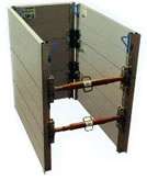
Lite-Shield Assembly
Choose a relatively flat, level space, close to the back hoe and excavation. Start construction of the shiled assembly with 2 panels, 2 panel connectors, (PC2-PC3 or PC4) and an adjustable strut.
Stand the two panels up, parallel with each other with the “V: groove side down, and spaced apart the length of the strut.
Use the keyway pins to attach the panel connectors to the panels. Install pin handles facing the inside of the shield. After installing the pins, be sure to rotate the handle downward in the locked position. Check if pin is secured by pulling on the handle. A PC2 connector should extend above the panel, one half of its length.
The PC 2 connector has four holes along one edge, and a single hole in the center of the other edge. Use two of the holes to pin the next panel in place. The single remaining hole is for the strut end.
Pin the strut in Place on the PC2’s between the two panels.
NOTE: All holes in the PC2 must have a pin installed.
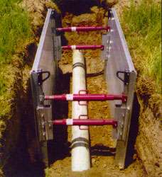
This sub-assembly will now stand up unaided, while you complete the shield. Continue construction by adding two more panel connectors to the opposite end of the shield and add a strut to that end also.
Add two more panels. It is easier to place the bottom edge of the next panel along the top edge of the previously constructed panel, with the top of the “loose” panel tilted outward 30% or so. When it is lined up, just “tilt” the panel up and into the panel connectors, and pin in place. Avoid “sliding” panels down into the connectors so as to avoid a pinch point.
Add two more PC2 connectors to each end of the newly added panels (4) and add a strut between these connectors at each end.
NOTE: Struts must be no further apart vertically than 4 feet, and must be within 2 feet of the top and bottom of the shield assembly. Consult tabulated data.
You may continue adding panels and struts in this manner. It is only practical to build the shield assembly to 8 feet high, in this fashion. Add the lift eyes to the four corners, and connect a four leg lift bridle. You are now ready to lift the Lite-Shield into the trench.
PC3 and PC4 connectors allow for easier construction of a “base” unit, either 6 feet or 8 feet high.
Note that these long connectors do not start at the bottom edge of the first panel, but rather halfway up, in the fashion of the PC2s.
Corner (manhole) connectors are used in the same way as the panel connectors, except that they accept a panel instead of a strut. They are used instead of the PC’s to construct a 3-or-4 sided closed end box. (Manhole, inlet, repair pit, etc.)